Welcome to visit: Anhong Energy-saving Explosion-proof Fan Co.


Tower-type low-noise local ventilation fan
Still deciding? If you are interested, you need to get a sample first,Contact us!
Product Category
FBD series
Tag
Mine ventilation equipment
- Product Description
-
The environmentally friendly, low-noise ventilation fan is a new product improved upon the basis of double noise reduction. According to the principle of noise generation and propagation, the air intake direction is changed, and by adsorbing low and medium frequency noise and effectively isolating high frequency sound, the overall sound of the ventilation fan is attenuated. The ventilation fan consists of a tower-type silencer, inlet and outlet silencers, a primary host, a secondary host, etc. (as shown in Figure 4). According to the testing by national authoritative departments, the noise can be lower than 80 decibels.
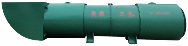
Environmentally friendly, low-noise local ventilation fan
FBD Series Product Introduction
1. Overview
The FBD series of explosion-proof, pressure-inlet, counter-rotating axial flow local ventilation fans (hereinafter referred to as ventilation fans) comply with MT222-2007 "Technical Conditions for Counter-Rotating Local Ventilation Fans" and Q/YAF001-2011 "FBD Series Explosion-proof, Pressure-inlet, Counter-rotating Axial Flow Local Ventilation Fans" standards. They are suitable for local ventilation in underground coal mines containing methane gas or coal dust and other environments with explosive hazards, and are used with positive pressure air ducts. They can also be used as ventilation equipment for tunnel construction. Specific details are as follows:
(1) The ventilation fan uses computational fluid dynamics for multi-objective overall optimization design. The blades use aviation engine FMIA airfoil, resulting in a large area of high-efficiency operating conditions. The ventilation fan features compact structure, large air volume, high air pressure, long air delivery distance, high efficiency, energy saving, and low noise.
(2) The ventilation fan is directly driven by two YBF2 series explosion-proof motors for fan use. To extend the service life of the fan, SKF series bearings from Sweden are used for the motor bearings. (Add bearing photo)
(3) According to the different needs of users, there are 3 types of silencers to choose from;
a) Ordinary outlet silencer; (Add photo)
b) Inlet and outlet combined silencer; (Add photo)
c) Side inlet, inlet and outlet combined silencer. (Add photo)
The third type (c) of combined silencer adds a side inlet component, which changes the airflow direction of the inlet without affecting the air intake, causing noise refraction. Coupled with the inlet and outlet silencers, this significantly reduces noise. Testing by the National Mine Equipment Testing Center shows that the noise level is reduced by 20-30 decibels compared to ordinary ventilation fans.
(4) The explosion-proof type of the ventilation fan and motor is: explosion-proof, and the explosion-proof mark is: ExdbI.
(5) The operating voltage is 380V/660V, 660V/1140V, and does not exceed ±5% of the rated value, and the voltage frequency is 50HZ.
For ventilation fans used underground, the roadway air supply should be greater than the maximum operating air volume of the ventilation fan.
The foundation for installing the ventilation fan should be firm and free from water splashing. The height of the edge of the ventilation fan's air inlet from the ground or top wall should be no less than 0.3m.
The air duct used should be able to withstand the highest pressure of the ventilation fan, and the diameter of the air duct should not be less than the diameter of the impeller.
(6) Service Life
The service life is no less than 5 years, and the safe operating time before the first overhaul is no less than 13000 hours.
2. Structural Features, Working Principle and Technical Parameters
(1) The ventilation fan consists of a collector, motor, primary fan, secondary fan, motor, silencer, etc. (Figure 1 with ordinary silencer; Figure 2 with inlet and outlet silencers; Figure 3 with side inlet combined silencer). The ventilation fan shell structural components are all welded from steel plates, the inner cylinder is welded from perforated steel plates, and lined with sound-absorbing material. The motor is connected to the air duct by flange joints with bolts. The motor casing and perforated steel plate serve as the inner air duct, and the two impellers rotate counter-rotationally at the same speed.
(2) Working Principle
The ventilation fan has two impellers, the first and second stage, each driven by two explosion-proof motors of the same capacity and model. The rotation directions of the two impellers are counter-rotating. Air enters the first-stage impeller, obtains energy, and is then discharged through the second-stage impeller. The second-stage impeller also has the function of the stationary blades in an ordinary axial flow fan. While obtaining the straightened circumferential velocity component, it also adds energy to the airflow, thus achieving the high efficiency and high air pressure that ordinary axial flow fans cannot achieve.
(3) The technical parameters of the ventilation fan are shown in Figures 1-3
Figure 1 Ventilation Fan Structural Diagram (with ordinary silencer)
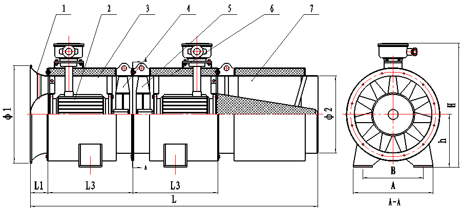
1. Collector, 2. Motor, 3. Primary host, 4. Primary impeller, 5. Secondary impeller, 6. Secondary host, 7. Outlet silencer
Machine Number
Motor Model
Power (kW)
Air Volume m³/min
Air Pressure (Pa)
L1
L3
L
Ф1
Ф2
A
B
h
H
Total Weight kg
4.0
YBF₂90L-2
2×2.2
200-110
300-1800
80
500
1680
490
410
400
280
310
740
280
YBF₂112M-2
2×4
220-120
350-2200
5.0
YBF₂132S-2
2×5.5
230-130
400-2750
120
580
1980
620
510
530
420
390
920
400
YBF₂132S-2
2×7.5
280-170
600-3200
6.0
YBF₂160M-2
2×11
380-220
700-3800
130
740
2340
740
610
700
580
410
1000
600
YBF₂160L-2
2×15
430-260
720-4300
6.3
YBF₂160L-2
2×18.5
500-350
750-4800
140
750
2370
780
640
720
600
435
1035
800
YBF₂180ML-2
2×22
550-360
850-5000
7.1
YBF₂200L-2
2×30
630-380
900-5900
150
840
2570
890
730
750
630
495
1145
1000
YBF₂200L-2
2×37
680-400
950-6100
8.0
YBF₂225M-2
2×45
780-440
1050-7500
160
1020
3000
950
820
800
680
530
1250
1450
YBF₂250M-2
2×55
900-540
1100-7800
YBF₂280S-2
2×75
1010-600
1600-8400
Figure 2: Ventilation system diagram (with inlet and outlet silencers)
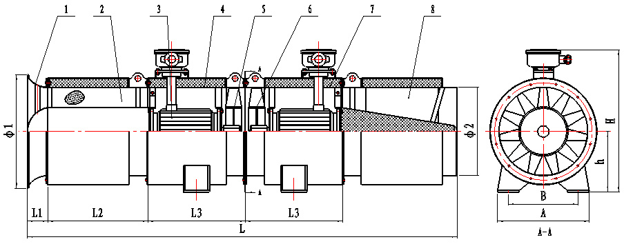
1. Collector, 2. Inlet silencer, 3. Motor, 4. Primary unit, 5. Primary impeller, 6. Secondary impeller, 7. Secondary unit, 8. Outlet silencer
Machine Number
Motor Model
Power kW
Air Volume m³/min
Air pressure Pa
L1
L2
L3
L
Ф1
Ф2
A
B
h
H
Total Weight kg
4.0
YBF₂90L-2
2×2.2
200-110
300-1800
80
600
500
2280
490
410
400
280
310
740
350
YBF₂112M-2
2×4
220-120
350-2200
5.0
YBF₂132S-2
2×5.5
230-130
400-2750
120
700
580
2680
620
510
530
420
390
920
480
YBF₂132S-2
2×7.5
280-170
600-3200
6.0
YBF₂160M-2
2×11
380-220
700-3800
130
730
740
3070
740
610
700
580
410
1000
700
YBF₂160L-2
2×15
430-260
720-4300
6.3
YBF₂160L-2
2×18.5
500-350
750-4800
140
730
750
3100
780
640
720
600
435
1035
920
YBF₂180ML-2
2×22
550-360
850-5000
7.1
YBF₂200L-2
2×30
630-380
900-5900
150
740
840
3310
890
730
750
630
495
1145
1150
YBF₂200L-2
2×37
680-400
950-6100
8.0
YBF₂225M-2
2×45
780-440
1050-7500
160
800
1020
3800
950
820
800
680
530
1250
1600
YBF₂250M-2
2×55
900-540
1100-7800
YBF₂280S-2
2×75
1010-600
1600-8400
Figure 3: Ventilation system diagram (with side inlet combined silencer)
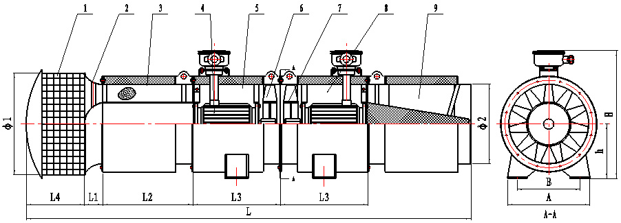
1. Side inlet device, 2. Collector, 3. Inlet silencer, 4. Motor, 5. Primary unit, 6. Primary impeller, 7. Secondary impeller, 8. Secondary unit, 9. Outlet silencer
Machine Number
Motor Model
Power kW
Air Volume m³/min
Air pressure Pa
L1
L2
L3
L
Ф1
Ф2
A
B
h
H
Total Weight kg
4.0
YBF₂90L-2
2×2.2
200-110
300-1800
80
600
500
2580
490
410
400
280
310
740
380
YBF₂112M-2
2×4
220-120
350-2200
5.0
YBF₂132S-2
2×5.5
230-130
400-2750
120
700
580
3010
620
510
530
420
390
920
520
YBF₂132S-2
2×7.5
280-170
600-3200
6.0
YBF₂160M-2
2×11
380-220
700-3800
130
730
740
3420
740
610
700
580
410
1000
750
YBF₂160L-2
2×15
430-260
720-4300
6.3
YBF₂160L-2
2×18.5
500-350
750-4800
140
730
750
3480
780
640
720
600
435
1035
970
YBF₂180ML-2
2×22
550-360
850-5000
7.1
YBF₂200L-2
2×30
630-380
900-5900
150
740
840
3710
890
730
750
630
495
1145
1200
YBF₂200L-2
2×37
680-400
950-6100
8.0
YBF₂225M-2
2×45
780-440
1050-7500
160
800
1020
4250
950
820
800
680
530
1250
1680
YBF₂250M-2
2×55
900-540
1100-7800
YBF₂280S-2
2×75
1010-600
1600-8400
3. Installation and commissioning
(1) Before assembly, the radial clearance between the top of the blade and the inner cylinder of the casing must be checked. The radial clearance should be between 1.5‰~3.5‰ of the impeller diameter, and not less than 1mm; there should be no axial clearance after assembly of each casing.
(2) The impeller rotation direction must conform to the direction indicated by the casing marking.
(3) The ventilation system must be managed and operated by a designated person.
(4) The installation and use of the ventilation system must comply with the relevant provisions of the "Coal Mine Safety Regulations", and the internal and external grounding wires must be securely connected before operation.
(5) The stripped connection of the motor lead-in wire should not exceed 1.5mm, and the motor should be installed according to the requirements of the motor instruction manual. Six terminals in the motor junction box can be used for two different voltages when changing the connection method (see Figure 2). The phase sequence U, V, W of the motor must correspond to the phase sequence A, B, C of the incoming external power supply. The motor rotation should be clockwise when viewed from the shaft extension end; otherwise, the motor will reverse.
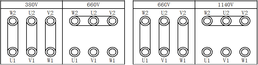
Figure 2: Motor wiring diagram (Note: Motor voltage levels are 380V/660V, 660V/1140V)
4. Use and operation
(1) Preparation and inspection before use
a) The cold-state insulation resistance between the motor stator winding and the frame should be measured and must be higher than 50MΩ; if it does not meet the requirements, drying treatment should be carried out.
b) Check for safety marks and explosion-proof certification numbers.
c) All explosion-proof surface parts have no cracks or defects that affect the explosion-proof performance (new motors that have not been disassembled can be omitted).
d) The incoming cable cores must be tightly fixed with wiring plates or U-shaped washers to prevent cable movement.
e) Check whether all fasteners are complete and secure, whether the connections are reliable, whether the trial operation is flexible, whether there are any abnormal noises or sounds, impact sounds, whether the impeller rotation direction is correct, and whether the grounding wire is connected.
(2) Instructions during use
a) To ensure the long-term safe operation of the ventilation system, attention should be paid to correct use and regular maintenance.
b) When starting, turn on the first-stage ventilation system first, and after running for 5 seconds, start the second-stage ventilation system.
c) During operation, regularly check whether the sound is normal and whether there is any loosening at the connections.
d) Motor maintenance should be carried out according to the provisions in the motor instruction manual.
e) The motor bearings should be checked at least once every 6 months of operation. If the bearing grease is found to be deteriorated or leaking, it must be replaced in time. Before replacement, the bearings must be cleaned with gasoline. Use ZL-3 lithium-based grease (Sy142-75), and the amount added should be 1/2 of the net volume of the bearing chamber. (For the 180000 series sealed bearings, the grease does not need to be replaced during the service life).
f) The bearing clearance during use should be within the allowable range, the operating temperature of the bearing should not exceed the allowable value, and the sound should be normal. When the bearing is worn or damaged, it should be replaced with a new bearing.
g) If the motor is damp, it must be dried.
h) After a period of use, coal dust may block the silencer holes, so it must be flushed with high-pressure airflow; otherwise, the fan noise will increase.
i) The fan should be inspected once a month, checking all parts of the machine.
j) When the fan is not in use, it should be placed in a well-ventilated and dry place to prevent dampness, corrosion, and other damage.
5. Fault Analysis and Troubleshooting
Table 1 Main Faults and Troubleshooting Methods
Fault Characteristics
Cause of Failure
Fault Identification and Troubleshooting Methods
Metallic collision sound inside the fan
Blade rubbing against the casing
Replace the blade or casing
Foreign object entry
Remove foreign objects
Motor bearing damage
Replace the motor or bearing
Bearing has a whistling sound (accompanied by temperature increase)
Too much, too little, or unclean lubricating grease
Reduce or add lubricating grease or clean the bearing
Lubricating grease aging or incorrect type
Replace the lubricating grease
Bearing vibration and internal collision sound
Too much lubricating oil or bearing fatigue wear
Reduce lubricating grease or replace bearing
Fan and motor vibration
Impeller imbalance
Replace the impeller
Insufficient foundation hardness and damage
Check the foundation
Flange connection bolts loose
Check all connecting bolts
Insufficient pressure or air volume
Air duct leakage or insufficient motor speed
Check for leaks or check the motor
Increased vibration, intermittent noise
Fan operating under unstable conditions
Check the fan intake and exhaust conditions
One or two stages of the fan stop running
Motor damage or power failure
Replace the motor or reconnect the power
Buzzing sound when power is on but not running
Incorrect phase sequence of the motor
Swap any two power lines
Fan starts with difficulty
Low power voltage or starter malfunction
Increase power voltage or check starter
6. Matters needing attention when using the fan
When using the fan in underground coal mines, the relevant regulations in the "Coal Mine Safety Regulations" must be strictly observed:
(1) The mining face using the fan must not stop ventilation. When ventilation is stopped due to power failure for maintenance, personnel must be evacuated and the power must be cut off.
(2) Before resuming ventilation, gas must be checked. Only when the gas concentration in the airflow within 10 meters of the fan and its switch does not exceed 0.5% can the local fan be manually started.
(3) If the fan stops running due to a fault, before resuming ventilation, the gas must first be checked. Only when the highest gas concentration in the stopped ventilation area does not exceed 1.0% and the highest carbon dioxide concentration does not exceed 1.5%, and the conditions in point 2 are met, can the fan be manually started to resume normal ventilation.
(4) When using a counter-rotating axial flow fan, both sets of impellers must be started simultaneously. If one motor is damaged, the entire machine must be stopped for maintenance, and single-stage start-up is not allowed.
Tower-type low-noise local ventilation fan
Still deciding? If you are interested, you need to get a sample first,Contact us!
Product Category
Tag
Mine ventilation equipment
Get a Quote
* Note: Please be sure to fill in the information accurately and keep the communication open. We will contact you as soon as possible.
Related Products


Service Hotline
Company Location
Yuncheng Airport Industrial Park, Shanxi Province
Please leave your contact information, and we will contact you within 24 hours.
Our Product Series

Yuncheng Anhong Energy-saving Explosion-proof Blower Co., Ltd. | Powered by 300.cn | Privacy Policy